Sourcekit® MeshMass TX6A4D
Designer: Weihong Guan , Shengyuan Fang, Donghao Chen
Overview
Sourcekit® MeshMass TX6A4D is a programmable remote control transmitter module designed for RC enthusiasts, STEM education, and the 3D printing community. It is the first product in the MeshMass series of affordable, programmable RC solutions.
The TX6A4D features dual joysticks, rotary knobs, and programmable buttons, making it ideal for building custom remote control systems for toys, brick builds, and 3D printed vehicles.
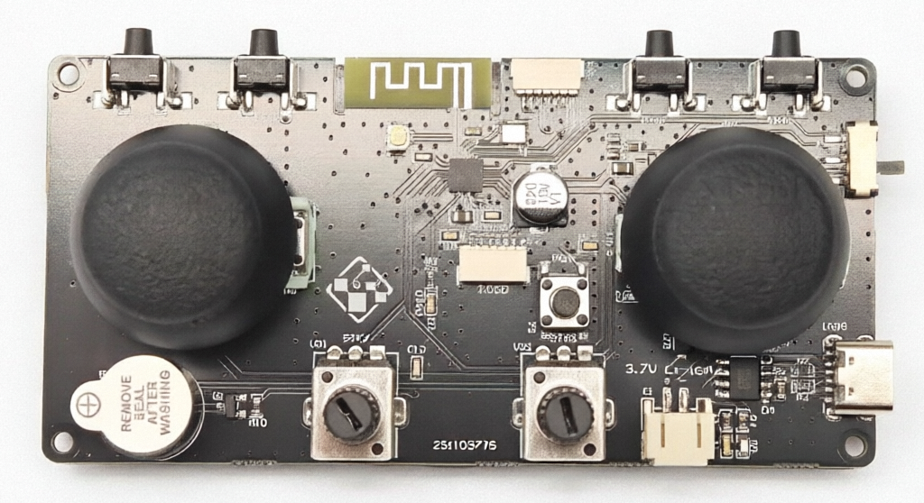
       ┌──┐     ┌──┐                                 ┌──┐     ┌──┐
┌────┬─└──┘─┬─┬─└──┘─┬──┬─────────────┬────┬────┬──┬─└──┘─┬─┬─└──┘─┬────┐
│    │ BTN0 │ │ BTN1 │  │ Onboard ANT │    │PROG│  │ BTN2 │ │ BTN3 │    │
│    └──────┘ └──────┘  └─────────────┘    └────┘  └──────┘ └──────┘┌───┌─┐
│                        ┌───┐                                      │PWR└─┘
│          STK2          │EXT│     SOURCEKIT             STK1       │ SW│
│            ▲           │ANT│     MeshMass                ▲        └───┤
│            │           └───┘     TX6A4D                  │            │
│     ◄──────┼──────► STK3                     STK0 ◄──────┼──────►     │
│            │                  ┌────┐ ┌────┐              │            │
│            ▼                  │OLED│ │PAIR│              ▼            │
│                               └────┘ └────┘                     ┌─────┤
│                       ┌──────┐         ┌──────┐      ┌────────┐ │ USB │
│ ┌──────┐              │      │         │      │      │DC Power│ │CHARGE
│ │BUZZER│              │ STK4 │         │ STK5 │      │3.7-4.2v│ └─────┤
│ └──────┘              │      │         │      │      │ +    - │       │
└───────────────────────┴──────┴─────────┴──────┴──────┴────────┴───────┘
Features
- Dual Joysticks: Two dual-axis joysticks providing 4 analog input channels
- Rotary Knobs: 2 knobs providing 2 analog input channels, programmable for throttle, speed or parameter adjustment
- Programmable Buttons: 4 shoulder buttons + 2 joystick press buttons for custom functions
- OLED Display Interface: 6-pin SH1.0 connector supports 128x64 SPI OLED (sold separately) showing battery voltage, signal strength, and raw input values
- Type-C Charging: Built-in charging circuit for 1S LiPo battery
- Antenna Options: Onboard PCB antenna + IPEX-1 socket for external 2.4GHz antenna
- Lost Connection Alarm: Buzzer alerts when connection to receiver is lost
- M2.5 Mounting: 4 mounting holes for secure installation
Specification
Microcontroller
The TX6A4D is powered by the WCH CH571F microcontroller from Nanjing WCH. This chip provides the core processing and wireless communication capabilities.
| Component | Specification |
|---|---|
| MCU | WCH CH571F (part of CH57x series) |
| Architecture | 32-bit RISC-V (QingKe V3A core) |
| CPU Speed | 48 MHz (typical) |
| Memory | 32KB SRAM, 256KB Flash |
| Wireless | 2.4GHz proprietary protocol (raw PHY layer for minimum latency) |
| ADC | 12-bit, 8 channels (6 used for joysticks/knobs) |
| GPIO | Multiple configurable I/O pins |
| Peripherals | SPI, UART |
The CH571F's RISC-V architecture provides efficient processing while the integrated 2.4GHz radio enables reliable wireless communication. The TX6A4D utilizes the raw 2.4GHz physical layer for minimum latency in real-time control applications.
Inputs
| Type | Count | Description |
|---|---|---|
| Analog | 6 | 4 from joysticks, 2 from knobs |
| Digital | 4 | 4 programmable shoulder buttons + 2 joystick press buttons (parallel-connected) |
| System | 1 | Pairing button (firmware-controlled) |
Note: Each joystick includes a built-in press button:
- Left Joystick Press: Connected in parallel with left edge button (Button 0 / BTN0,
getButton(0)) - Right Joystick Press: Connected in parallel with right edge button (Button 3 / BTN3,
getButton(3)) |
Power
| Specification | Value |
|---|---|
| Battery | 1S LiPo (3.7V - 4.2V) |
| Battery Connector | PH2.0 |
| Charging | Type-C USB |
| Warning | Ensure correct battery polarity (+/-) or damage may occur |
Physical
| Specification | Value |
|---|---|
| Dimensions | 100mm x 50mm |
| Mounting | 4x M2.5 holes |
| Weight | TBD |
Display & Feedback
| Component | Description |
|---|---|
| Display Interface | 6-pin SH1.0 connector, SPI interface for 128x64 OLED (sold separately with cable) |
| Programming Interface | 6-pin SH1.0 connector for MeshMass USB Flashing Dongle (sold separately with cable), also provides serial console output (OLED display recommended for visual debugging) |
| Display Shows | Battery voltage, wireless signal strength (both ends), and raw input values (6 analog: 0-255, 4 digital: 0/1) |
| Buzzer | Lost connection alarm |
Display Note: MeshMass shows raw decimal values (not scroll bars or progress indicators) for precise verification. Students can directly see how their code translates physical inputs to numerical outputs. The transmitter OLED displays system status (battery voltage, signal strength) since the user holds it in hand, while the receiver OLED focuses on output debugging. The OLED screen is sold separately, making it optional for fixed installations and friendly to budget-conscious builders.
Connectivity
| Feature | Description |
|---|---|
| Wireless | 2.4GHz auto-hopping (BLE PHY layer only, no GATT) |
| Antenna | Onboard PCB antenna + IPEX-1 connector for external 2.4GHz antenna |
| Range | ~40 meters in open field (onboard PCB antennas), extends with external antenna |
Pairing
The TX6A4D follows the standard MeshMass pairing system described in the MeshMass Introduction. Key details specific to the TX6A4D:
- The pairing button is labeled "PAIR" on the PCB, separate from the programmable shoulder buttons (BTN0-BTN3)
- It's controlled by firmware and cannot be reprogrammed for other functions
- The OLED display shows pairing status and confirmation
For complete pairing instructions including EEPROM storage, one-to-one exclusive pairing, and the detailed pairing process, refer to the Pairing System section in the MeshMass Introduction.
Development Guide
The TX6A4D is programmable via the MeshMass online platform at meshmass.com (global access) or meshmass.y77.cc (China mainland) using a web browser and the MeshMass USB flashing dongle (sold separately). The CH571F runs pre-built firmware scaffolds that handle low-level RF communication, while users focus on application-level input mapping logic.
Note: The TX6A4D USB-C port is for charging only. Firmware flashing requires the separate USB dongle.
Programming Philosophy
MeshMass adopts a code-based programming approach that combines open hardware flexibility with consumer product accessibility. For detailed discussion of design philosophy, competitive advantages, educational value, and system architecture, see the MeshMass Introduction page.
Key advantages for TX6A4D:
- Simple C API for mapping physical inputs to wireless channels
- Web-based programming with immediate visual feedback via OLED
- One stock program that works with every vehicle you build
What you program: In practice, most people program the TX6A4D once. The stock program forwards all six analog inputs and four buttons onto channels, and that is all a controller needs to do — the vehicle's behaviour is written on the receiver. You would come back here only to do something that genuinely belongs to the controller, such as sending a mode selection on a spare channel.
Hardware model vs. firmware name
TX6A4D is the hardware model — the board you bought. On the MeshMass platform the firmware for it is published as the TX6AX course, "TX6A4D Raw Firmware — broadcasting the raw inputs".
It pairs with RX4MX ("RX4M4S Fusion Firmware") on the receiver side, and that pairing is what all current lessons are written against. Modules bought on their own ship with it.
If you bought a finished kit from a model designer, it arrived pre-flashed with whatever that particular kit needs, which may be an earlier firmware — it will simply work as sold. Check what is on the boards before re-flashing, and if you do move to the current firmware, flash both ends together.
Firmware Architecture
The TX6A4D runs a pre-built firmware scaffold that handles low-level hardware operations while exposing a simple API for application programming. This architecture separates hardware complexity from application logic, allowing users to focus on channel mapping.
Channel System
The firmware defines 16 single-byte wireless channels. These channels form the communication bridge between transmitter and receiver. Applications map physical inputs (joysticks, knobs, buttons) to these channels, which are then transmitted wirelessly to paired receivers.
Analog inputs are read as raw unsigned values (0-255) straight from each input's own ADC channel, compensated for battery droop, with roughly 128 at the centre or neutral position. The transmitter applies no centring, deadzone, scaling or mixing of its own — it forwards what it measures, and the receiver decides what it means.
PCB Labels: The PCB is labeled with STK0-STK5 for analog inputs and BTN0-BTN3 for digital buttons, corresponding directly to API indices.
Analog Input Mapping (via getStick(n)):
| Index | PCB Label | Physical Input | Description |
|---|---|---|---|
| 0 | STK0 | Right Joystick X-axis | Left/right movement of right stick |
| 1 | STK1 | Right Joystick Y-axis | Up/down movement of right stick |
| 2 | STK2 | Left Joystick Y-axis | Up/down movement of left stick |
| 3 | STK3 | Left Joystick X-axis | Left/right movement of left stick |
| 4 | STK4 | Knob Left | Rotary knob, typically for throttle |
| 5 | STK5 | Knob Right | Rotary knob, typically for parameter |
Digital Input Mapping (via getButton(n)):
| Index | PCB Label | Physical Input | Description |
|---|---|---|---|
| 0 | BTN0 | Button 0 (left edge) | Programmable shoulder button + left joystick press |
| 1 | BTN1 | Button 1 (left middle) | Programmable shoulder button |
| 2 | BTN2 | Button 2 (right middle) | Programmable shoulder button |
| 3 | BTN3 | Button 3 (right edge) | Programmable shoulder button + right joystick press |
| - | PAIR | Pairing Button | System button (firmware-controlled) |
Note: Joystick press buttons are connected in parallel with shoulder buttons:
- Left Joystick Press: Activates
getButton(0)(same as Button 0 / left edge button) - Right Joystick Press: Activates
getButton(3)(same as Button 3 / right edge button) |
Timing and Execution
Execution Model: The loop() function is called every 20ms (50Hz) by the firmware scaffold. This matches the typical update frequency of analog servos, ensuring smooth control updates.
Firmware Cycle Details: Before each loop() call, the firmware automatically refreshes all analog inputs (joysticks, knobs) and digital inputs (buttons), storing their latest values in memory. The getStick() and getButton() functions return these pre-fetched values. During loop(), setChannel() updates values in a 16-byte transmission frame buffer. Channels not explicitly set retain their previous values. After loop() completes, the entire 16-byte frame buffer is broadcast wirelessly.
Important: Avoid using busy-waiting or delay functions inside loop(). The firmware runs a Real-Time Operating System (RTOS) in the background. Blocking operations can prevent critical system tasks from running, potentially causing system failures or unpredictable behavior.
Application Code Examples
Architecture Note: The code on the transmitter only controls the mapping from physical inputs (joysticks, knobs, buttons) to wireless channels. How those channel values become motor and servo movement is determined by the application code running on the receiver.
Note: The app.h header file already includes <stdbool.h> and <stdint.h> headers, so you don't need to include them in your application code. On meshmass.com, you can view the app.h file for reference, but it's not recommended to edit it.
The stock program forwards every input unchanged — six analog inputs to channels 0-5, four buttons to channels 6-9:
#include "app.h"

void loop() {
  setChannel(0, getStick(0));
  setChannel(1, getStick(1));
  setChannel(2, getStick(2));
  setChannel(3, getStick(3));
  setChannel(4, getStick(4));
  setChannel(5, getStick(5));

  setChannel(6, getButton(0));
  setChannel(7, getButton(1));
  setChannel(8, getButton(2));
  setChannel(9, getButton(3));
}
That is deliberately the whole program. Centring, deadzone, scaling, reversing and mixing all belong on the receiver, which knows what the outputs are wired to — see Centring a stick channel on the RX4M4S page.
Why shape the signal on the receiver?
A transmitter that has already centred and mixed its sticks has thrown away information the receiver cannot recover. More importantly, the two ends of the link are not symmetrical: your controller always looks the same, while the receiver ends up bolted into a tank one week and an excavator the next. A tank mixes the same two sticks quite differently from an excavator — and with Neopixel lights and an audio module also on the receiver, that end decides when brake lights come on and when the engine note changes.
Keeping all of it on the receiver means one controller program serves every vehicle, and changing a vehicle means editing one program on one board instead of two.
You can still do work here when it genuinely belongs to the controller — for instance, using a button to select a mode and sending that mode on a spare channel, so the vehicle switches behaviour without you reflashing it. Channels 10-15 are unused by the stock program and free for this.
Quick Reference
Core Functions:
getStick(n)- Read analog input (joystick/knob) as a raw unsigned0-255reading, ~128at centregetButton(n)- Read digital button state (true/false)setChannel(n, value)- Set wireless channel valuegetChannel(n)- Get current channel valueloop()- Main application function called every 20ms
Channels carry a raw byte
setChannel() is declared as taking a signed int8_t, but a channel is really just one byte on the wire. Passing getStick() straight into it is correct and is what the stock program does: values above 127 wrap to negative on the transmitter side, and the receiver reads the byte back unchanged as 0-255 via getChannel(). Don't try to "fix" the sign here — recentre on the receiver instead.
For complete function documentation with parameters, return values, and usage notes, see the API Reference section below.
State Persistence: Variables that need to retain values between loop() calls should be declared as static inside loop() or as global variables outside functions.
Standard Library: Common C standard library functions like abs() are available for mathematical operations.
API Reference
TX6A4D Application Header File
#ifndef APP_H
#define APP_H

#include <stdint.h>
#include <stdbool.h>

/**
 * Read digital button state.
 *
 * @param index Button index (0-3):
 * • 0: Button 0 (left edge) / Left joystick press
 * • 1: Button 1 (left middle)
 * • 2: Button 2 (right middle)
 * • 3: Button 3 (right edge) / Right joystick press
 * @return true if button is pressed, false otherwise
 */
bool getButton(uint8_t index);

/**
 * Read analog input value.
 *
 * @param index Analog input index (0-5):
 * • 0: Right joystick X-axis (STK0)
 * • 1: Right joystick Y-axis (STK1)
 * • 2: Left joystick Y-axis (STK2)
 * • 3: Left joystick X-axis (STK3)
 * • 4: Left knob (STK4)
 * • 5: Right knob (STK5)
 * @return Raw unsigned 8-bit reading (0 to 255) from the input's own ADC
 * channel, VBat-compensated for battery droop. ~128 is the center/neutral
 * position; 0 and 255 are the travel extremes.
 */
uint8_t getStick(uint8_t index);

/**
 * Set wireless channel value.
 *
 * @param index Channel index (0-15)
 * @param value Signed 8-bit value (-128 to 127) to assign to channel.
 * While getStick() avoids -128, setChannel() can use it for
 * special purposes (e.g., braking in motor control).
 */
void setChannel(uint8_t index, int8_t value);

/**
 * Get current wireless channel value.
 *
 * @param index Channel index (0-15)
 * @return Current signed 8-bit value (-128 to 127) of the channel
 */
int8_t getChannel(uint8_t index);

/**
 * Application main loop function.
 *
 * Called every 20ms (50Hz) by the firmware scaffold. Implement this function
 * to define your control logic mapping inputs to wireless channels.
 *
 * Important: Avoid busy-waiting or delay functions. The firmware runs a
 * Real-Time Operating System (RTOS) in the background.
 *
 * After loop() completes, the firmware broadcasts all 16 channel values
 * wirelessly to paired receivers. Channels not explicitly set in loop()
 * retain their previous values.
 */
void loop();

#endif
Firmware-Managed Features
The scaffold handles several system functions automatically:
- OLED Display: Real-time debugging display showing battery voltage, wireless signal strength for both ends of the link, and all input values (6 analog:
0-255, 4 digital:0/1). Because the analog readings are shown exactly as they are transmitted, you can compare the number on the transmitter against the channel value on the receiver's own display and confirm the link end to end. Displays raw decimal values (not simplified visualizations) for precise code verification. The OLED is sold separately, making it optional for fixed installations while maintaining budget-friendly flexibility. - Buzzer: Provides lost connection alarms and system feedback
- Wireless Communication: Manages 2.4GHz packet transmission with auto-hopping
- Battery Management: Monitors voltage and provides low-battery warnings
This separation allows users to focus on application logic (channel mapping) while the firmware handles hardware complexities.
System Architecture
MeshMass separates transmitter and receiver concerns:
- TX6A4D (Transmitter): Maps physical inputs (joysticks, knobs, buttons) to 16 wireless channels
- RX4M4S (Receiver): Maps received channels to physical outputs (motors, servos)
This abstraction lets users focus on what matters most for their specific build without worrying about RF protocol details. The transmitter defines what to send (channel values), while the receiver defines how to actuate (motor/servo outputs).
Applications
Sample applications and code templates are available on meshmass.com for:
- Construction vehicles (Forklift, Dump Truck, Excavator)
- RC cars and trucks
- Cranes and manipulators
- Custom 3D printed vehicles
- Small scale RC airplanes and drones
- Sandbox models and dioramas
- STEM education projects
- Custom robotics and automation
3D Printing & Customization
The TX6A4D is designed with the 3D printing community in mind. Community members have created custom designs to enhance your building experience:
- 3D Printed Case Design: CDHCHAOREN has designed a 3D printable case for the TX6A4D. The STL file is available for download on MakerWorld. This simple enclosure protects the electronics and provides mounting support (requires 3D printer and filament).
The TX6A4D's M2.5 mounting holes make it easy to integrate into custom 3D printed enclosures or vehicle designs. Share your creations with the community!
Discussion and Show Cases
- Forum (Powered by GitHub Discussion)
- bilibili - CDHCHAOREN - Programmable RC module
- MakerWorld - 3D printed case for TX6A4D by CDHCHAOREN
Where to Buy
Related Products
- RX4M4S Receiver - 4 DC Motor + 4 Servo receiver module
- Mini Tank Starter Kit - Complete 3D-printable tank kit using TX6A4D + RX4M4S, with teacher's guide
- USB Flashing Dongle - Browser-based programming tool (coming soon)