Sourcekit® MeshMass RX4M4S
Designer: Weihong Guan , Shengyuan Fang, Donghao Chen
Overview
Sourcekit® MeshMass RX4M4S is a programmable receiver module designed for RC applications. It is the companion receiver to the TX6A4D transmitter, forming a complete programmable RC control system.
The RX4M4S provides 4 DC motor outputs and 4 servo outputs, making it ideal for controlling complex vehicles like construction equipment, RC cars, cranes, and custom 3D printed builds. Designed with 3D printing hobbyists in mind, it offers space-efficient integration, built-in motor drivers, and easy programming through a web-based editor.
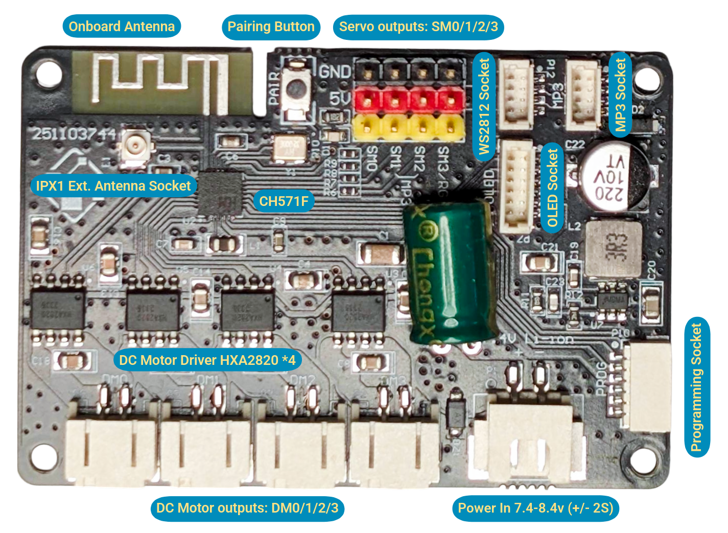
┌─────┬───────────────────┬──────────┬───┬───┬───┬───┬──┬───┬─┬───┬─────┐
│     │    Onboard        │  ┌────┐  │   │   │   │   │  │ R │ │ M │     │
│     │        Antenna    │  │PAIR│  │ S │ S │ S │ S │  │ G │ │ P │     │
│     └───────────────────┘  └────┘  │ M │ M │ M │ M │  │ B │ │ 3 │     │
│         ┌───┐                      │ 0 │ 1 │ 2 │ 3 │  └───┘ └───┘     │
│         │Ext│                      │   │   │   │   │  ┌───┐           │
│         │Ant│                      └───┴───┴───┴───┘  │ O │           │
│         └───┘                                         │ L │           │
│                     SOURCEKIT                         │ E │           │
│                     MeshMass                          │ D │       ┌───┤
│                     RX4M4S                            └───┘       │ P │
│                                                                   │ R │
│                                                     ┌────────────┐│ O │
│    ┌─────────┐ ┌─────────┐ ┌─────────┐ ┌─────────┐  │            ││ G │
│    │         │ │         │ │         │ │         │  │  DC Power  │└───┤
│    │   DM0   │ │   DM1   │ │   DM2   │ │   DM3   │  │  7.4-8.4v  │    │
│    │         │ │         │ │         │ │         │  │   +    -   │    │
└────┴─────────┴─┴─────────┴─┴─────────┴─┴─────────┴──┴────────────┴────┘
Features
- 4 DC Motor Outputs: For brushed DC motor control (N20, 370, etc.)
- 4 Servo Outputs: 50Hz PWM outputs (5V, compatible with 9g servos and more)
- Programmable Channel Mapping: Map any of the 16 wireless channels to any output
- Mixing Support: Combine multiple channels for complex behaviors (tank steering, crane controls)
- OLED Display Interface: 6-pin SH1.0 connector for 128x64 SPI OLED (sold separately)
- WS2812 Neopixel Interface: 4-pin SH1.0 connector for addressable RGB LED strips (vehicle head/turning/tail lights). Shares signal pin with SM3 (not included, enabled by a switch in the firmware)
- Audio Module Interface: 4-pin SH1.0 connector for optional audio module (MP3 playback for engine start sound effects). Shares pins with SM1, SM2 (sold separately)
- Low Latency: 2.4GHz proprietary protocol optimized for real-time control
- External Antenna Option: IPEX-1 connector for external 2.4GHz antenna
- Compact Design: Easy to integrate into custom builds
Specification
Microcontroller
The RX4M4S is powered by the same WCH CH571F microcontroller as the TX6A4D transmitter, ensuring full protocol compatibility and optimized performance.
| Component | Specification |
|---|---|
| MCU | WCH CH571F (part of CH57x series) |
| Architecture | 32-bit RISC-V (QingKe V3A core) |
| CPU Speed | 48 MHz (typical) |
| Memory | 32KB SRAM, 256KB Flash |
| Wireless | 2.4GHz proprietary protocol (raw PHY layer for minimum latency) |
| GPIO | Multiple configurable I/O pins |
| PWM | Hardware PWM outputs (used for WS2812 LED control) |
| Timer | Advanced timer for servo PWM generation |
| Peripherals | SPI, UART |
The CH571F's advanced timer capabilities are particularly important for the RX4M4S, enabling precise servo PWM signal generation with minimal CPU overhead. Like the TX6A4D, the receiver utilizes the raw 2.4GHz physical layer for minimum latency in real-time control applications.
Outputs
| Type | Count | Connector | Description |
|---|---|---|---|
| DC Motor | 4 | PH2.0 | Brushed DC motor driver outputs with ~220Hz PWM (DM0-DM3) |
| Servo | 4 | 2.54mm servo header (3-pin) | 50Hz PWM servo outputs (5V) |
| WS2812 Neopixels | 1 (shared) | 4-pin SH1.0 | Addressable RGB LED strips for vehicle lights (head/turning/tail). Shares signal pin with SM3 (not included, enabled by a switch in the firmware) |
| Audio Module | 1 (optional) | 4-pin SH1.0 | MP3 playback for sound effects (engine start, horns). Shares pins with SM1, SM2 (sold separately) |
Motor Outputs (DM0-DM3):
- 4x PH2.0 connectors for brushed DC motors
- Driven by 4x HXA2820 H-bridge motor drivers (one per channel)
- HXA2820 specifications:
- Max working voltage: 10.5V (compatible with 2S LiPo)
- Max continuous current: 2A per channel
- Max peak current: 3.5A
- Overtemperature protection: 150°C
- Key Advantage: Built-in motor drivers eliminate the need for external ESCs or motor driver boards. Most RC receivers require separate electronic speed controllers (ESCs) for each DC motor, adding cost, weight, and wiring complexity. The RX4M4S integrates 4 motor drivers directly on the board.
- Supports a wide range of low-voltage brushed DC motors (3V-7.4V, 2S LiPo range):
- Micro motors: N20, 610, 716, 718 (micro robots, small mechanisms)
- Coreless motors: 8515, 8520, 1020, 1220 (high-speed, fast response)
- Standard RC motors: 130, 140, 180, 260, 270, 280 series (1/10 scale vehicles)
- Medium motors: R300, 350, 370, 380, 390 series (higher torque applications)
- Gear motors: Any of the above with gearbox reduction for precise control
- PWM speed control (~220Hz) with bidirectional control and braking capability
Technical Note: The RX4M4S generates two types of PWM signals:
- Motor PWM: ~220Hz frequency for smooth motor speed control. Each DC motor channel uses two complementary PWM outputs to drive the H-bridge for bidirectional control with braking.
- Servo PWM: 50Hz (20ms period) standard servo control. Each servo channel uses one PWM output for position control.
Servo Outputs (SM0-SM3):
- 4x standard 2.54mm servo headers (3-pin, Dupont style) for standard servos
- Pinout: GND (black) / 5V (red) / Signal (yellow)
- 5V power supply for servos
- Compatible with 9g servos and standard analog/digital servos
- PWM signal: 50Hz (20ms frame), programmable pulse width (typically 1000-2000μs, supports 500-2500μs for extended range servos)
Pin Sharing & Board Configuration: The four servo headers are shared with the accessory interfaces. The WS2812 Neopixel interface (for vehicle head/turning/tail lights) uses the SM3 signal pin. The audio module interface (for MP3 sound effects like engine start) uses the SM1 and SM2 pins. A header can serve one purpose at a time, so fitting an accessory costs you the servo channels it occupies.
One firmware covers every combination. The receiver firmware — published on the MeshMass platform as the RX4MX course, "RX4M4S Fusion Firmware" — is config-driven: you declare which accessories are fitted with two switches at the top of Project/inc/app.h, and everything else is derived from them.
#define AUDIO_ON_SM1_SM2 0   // 1 = MP3 audio module on SM1 + SM2
#define NEO_ON_SM3       0   // 1 = WS2812 neopixel strip on SM3
The two switches give four board shapes:
AUDIO_ON_SM1_SM2 | NEO_ON_SM3 | DC Motors | Servo headers available | Neopixel | Audio |
|---|---|---|---|---|---|
0 | 0 | 4 | SM0 SM1 SM2 SM3 (4) | — | — |
0 | 1 | 4 | SM0 SM1 SM2 (3) | SM3 | — |
1 | 0 | 4 | SM0 SM3 (2, sparse) | — | SM1 + SM2 |
1 | 1 | 4 | SM0 (1) | SM3 | SM1 + SM2 |
All four DC motor outputs are always available — the switches only affect the servo headers.
Servo indices are header labels, not a sequence
setServo(index, …) addresses the header by its silkscreen label, not by its position among the remaining servos. In the sparse row above (audio fitted, no neopixel) the valid indices are 0 and 3 — there is no servo 1 or 2. Calls to a header that isn't a servo on your configuration are silently ignored.
One firmware, one course, one set of lessons — you configure the board rather than hunting for the right build.
Power
| Specification | Value |
|---|---|
| Input Voltage | 2S LiPo (7.4V - 8.4V) |
| Battery Connector | XH2.54 |
| Servo Power | 5V regulated output |
| Motor Power | Direct battery input (2S) |
| Warning | Only supports 2S LiPo battery. Using other voltage may damage the board. |
Physical
| Specification | Value |
|---|---|
| Dimensions | 40mm × 60mm |
| Mounting | 4× M2.5 mounting holes |
| Weight | ~15g (without connectors) |
| PCB Color | Black |
Display & Feedback
| Component | Description |
|---|---|
| Display Interface | 6-pin SH1.0 connector, SPI interface for 128x64 OLED (sold separately) |
| Programming Interface | 6-pin SH1.0 connector for MeshMass USB Flashing Dongle (sold separately), also provides serial console output |
| Display Shows | Debugging values on a 4-line OLED: received channel values (unsigned 0-255), the 4 motor outputs (signed, with sign), and the 4 servo headers |
Display Note: MeshMass shows raw decimal values (not scroll bars or progress indicators) for precise verification. Channel values appear as received — unsigned 0-255, resting near 128 for a centred stick — while motor outputs are shown signed so direction is visible at a glance. This lets students watch a stick's raw number on one line and the recentred, mixed, scaled motor value on another, debugging the maths between them.
Servo headers that a module has claimed show the module instead of a number: SM1 and SM2 read MP3 --- when the audio module is enabled, and SM3 reads RGB when the neopixel output is enabled — a quick way to confirm the firmware switches match the hardware actually fitted.
The OLED screen is sold separately, making it optional for fixed installations and friendly to budget-conscious builders.
Connectivity
| Feature | Description |
|---|---|
| Wireless | 2.4GHz auto-hopping (BLE PHY layer only, no GATT) |
| Protocol | Proprietary low-latency RC protocol |
| Pairing | One-to-one binding with TX6A4D via pairing procedure |
| Antenna | Onboard PCB antenna + IPEX-1 connector for external 2.4GHz antenna |
| Range | ~40 meters in open field (onboard PCB antennas), extends with external antenna |
Pairing
The RX4M4S follows the standard MeshMass pairing system described in the MeshMass Introduction. Key details specific to the RX4M4S:
- The pairing button is labeled "PAIR" on the PCB
- It's controlled by firmware and cannot be reprogrammed for other functions
- The OLED display shows pairing status and confirmation
For complete pairing instructions including EEPROM storage, one-to-one exclusive pairing, and the detailed pairing process, refer to the Pairing System section in the MeshMass Introduction.
Development Guide
The RX4M4S is programmable via the MeshMass online platform at meshmass.com (global access) or meshmass.y77.cc (China mainland) using a web browser and the MeshMass USB flashing dongle (sold separately). The CH571F runs pre-built firmware scaffolds that handle low-level RF communication and hardware drivers, while users focus on application-level output mapping logic.
Open a lesson, edit the code in the browser, build it, and flash the result — no account required. The toolchain and the firmware core live on the server, so there is nothing to install.
Your edits are not saved
The platform builds whatever source you submit, but it does not store it. Edits you make in the browser are lost when you leave the page or reload it — keep your own copy of any code you want to keep. For a classroom, that means having students paste their work somewhere durable before the session ends.
Note: The RX4M4S does not have a built-in charging circuit. Programming and power are supplied through separate connectors.
What you program: On RX4M4S, you define how received wireless channels map to motor, servo, and RGB LED outputs. How these channels are generated is determined by the transmitter (TX) firmware.
- Map any of the 16 wireless channels to motor, servo, and RGB LED outputs
- Create mixing functions (e.g., differential steering, crane articulation)
- Configure motor direction and speed curves
- Set servo travel limits, center points, and exponential response
- Implement custom logic for buttons and switches
The MeshMass system is built on a code-based programming approach that combines the flexibility of open hardware with the accessibility of consumer products. For detailed discussion of our design philosophy, competitive advantages, educational value, and system architecture, see the MeshMass Introduction page.
Key advantages for RX4M4S:
Built-in Motor Drivers
- Integrates 4 HXA2820 H-bridge motor drivers directly on the board
- Eliminates need for external ESCs or motor driver boards
- 10.5V max, 2A continuous, 3.5A peak per channel
- Brake capability for precise control
- Supports wide range: N20 micro motors to 370 series medium motors
Pin Sharing & Board Configuration
- One firmware (
rx4mx) covers every accessory combination — two switches inapp.h, no separate builds - WS2812 Neopixels use the SM3 signal pin (lights or servo SM3, not both)
- Audio module uses the SM1 and SM2 pins (sound effects or servos SM1/SM2, not both)
Scaffold Programming Approach
- Low-level RF, timing, and driver code pre-built
- Focus on application logic and output mapping
- Safety features and connection loss handling built-in
Real-time Performance
- 50Hz update rate matches servo refresh
- Minimum latency wireless communication
- Event-driven loop() for responsive control
Easy Visual Debugging
- Firmware verification without plugging in executors (which can be powerful but dangerous)
- Transmitter displays battery voltage and signal strength (user holds it in hand)
- Receiver displays debugging values: channels, motor outputs, servo outputs (for mapping verification)
- Aligns with usage patterns: transmitter in hand for system status, receiver remote for output verification
Firmware Architecture
The RX4M4S runs a pre-built firmware scaffold that handles low-level hardware operations while exposing a simple API for application programming. This architecture separates hardware complexity from application logic, allowing users to focus on output mapping.
Channel System
The firmware receives 16 raw bytes as wireless channels from the paired transmitter, read with getChannel(index) for index 0–15. Application code interprets these channel values and maps them to motor, servo, and RGB LED outputs based on the specific vehicle's requirements.
Channels carry raw, uncentred readings. getChannel() returns an unsigned value 0–255. Stick and knob channels carry the transmitter's raw ADC position, with roughly 128 at centre; button channels carry 0 or 1. The transmitter does no centring, deadzone, scaling, or mixing — the receiver owns all of it. Feeding a stick channel straight into setMotor() would read the resting centre as a large positive value and drive the motor at speed, so stick channels are almost always passed through a centring helper first (see Centring a stick channel below).
Note: The channel values received are exactly the bytes the transmitter sends. The transmitter only controls the mapping from physical inputs to channels. How those values become motor, servo, and RGB LED outputs is determined entirely by the application code running on the receiver.
Default channel map
What each channel carries is decided by the transmitter's program. The stock TX6A4D program forwards its inputs unchanged, giving this layout:
| Channel | Source | Value |
|---|---|---|
0 | Right joystick X (horizontal) | 0–255, ~128 centred |
1 | Right joystick Y (vertical) | 0–255, ~128 centred |
2 | Left joystick Y (vertical) | 0–255, ~128 centred |
3 | Left joystick X (horizontal) | 0–255, ~128 centred |
4 | Left knob | 0–255 |
5 | Right knob | 0–255 |
6 | Button 0 | 0 / 1 |
7 | Button 1 | 0 / 1 |
8 | Button 2 | 0 / 1 |
9 | Button 3 | 0 / 1 |
10–15 | Unused | 0 |
The physical direction each end of the range corresponds to:
| Input | At 0 | At 255 |
|---|---|---|
| Joystick horizontal (X) | Right | Left |
| Joystick vertical (Y) | Down | Up |
| Knob | Fully anticlockwise | Fully clockwise |
So once a stick channel is recentred, positive means left or up, negative means right or down.
Centring a stick channel
Because stick channels arrive raw (0–255, centre near 128) and setMotor() expects a signed -127–127, every receiver program needs to recentre them. The reference firmware ships a small centered() helper for exactly this, and the lessons all reuse it:
// Center a raw 0..255 stick to a signed -127..+127 swing. The base is a 1:1
// map (0..126 -> -127..-1, 129..255 -> 1..127, center codes 127/128 -> 0),
// bounded to ±127 by construction. The deadzone widens the neutral band and
// rescales the remaining travel so a full-throw stick still reaches ±127;
// deadzone 0 leaves the pure 1:1 map.
static int8_t centered(uint8_t index, uint8_t deadzone) {
  int16_t r = getChannel(index);
  int16_t s = r <= 127 ? r - 127 : r - 128;
  if (s > deadzone) return (s - deadzone) * 127 / (127 - deadzone);
  if (s < -deadzone) return (s + deadzone) * 127 / (127 - deadzone);
  return 0;
}
The mapping it produces:
| Raw channel value | centered() output |
|---|---|
0 – 126 | -127 – -1 |
127 / 128 | 0 |
129 – 255 | +1 – +127 |
The deadzone argument widens the neutral band around centre, then rescales the remaining travel so a full-throw stick still reaches the extremes:
deadzone | Raw values that output exactly 0 | Full-throw output |
|---|---|---|
0 | 127 / 128 (centre only) | ±127 |
8 | 119 – 136 | ±127 |
20 | 107 – 148 | ±127 |
Use a small deadzone (around 8) on motor channels so a slightly off-centre stick doesn't creep, and centered(index, 0) for servo channels where you want the output to park at an exact centre value.
Application Code Examples
Timing Note: The loop() function is called by the firmware scaffold after each successfully received and verified wireless payload from the paired transmitter. Since the transmitter broadcasts at 50Hz (every 20ms), the receiver typically calls loop() at 50Hz under normal connection conditions. This matches the typical update frequency of analog servos and ESCs, ensuring smooth control updates.
Firmware Cycle Details: After each loop() call completes, the motor and servo outputs are updated with the new values. Motor outputs use ~220Hz PWM for speed control, while servo outputs use 50Hz PWM signal (center ~150, range approximately 100-200) for position control.
Important: Avoid using busy-waiting or delay functions inside loop(). The firmware runs a Real-Time Operating System (RTOS) in the background. Blocking operations can prevent critical system tasks from running, potentially causing system failures or unpredictable behavior.
The default program
Out of the box, the receiver runs the four stick channels through centered() with a deadzone of 8 to drive the four motors, and drives two mirrored servo pairs from the knob channels. centered() is the helper shown above.
#include "app.h"

void loop() {
  setMotor(0, centered(0, 8));
  setMotor(1, centered(1, 8));
  setMotor(2, centered(2, 8));
  setMotor(3, centered(3, 8));

  // Knob channels 4 and 5 each drive a mirrored servo pair around center
  // (150 = 1.5 ms): SM0/SM1 follow the knob, SM2/SM3 mirror it. Reusing
  // centered(…, 0) parks both at exactly 150 when the knob is centered.
  setServo(0, 150 + centered(4, 0) * 2 / 5);
  setServo(1, 150 + centered(5, 0) * 2 / 5);

  setServo(2, 150 - centered(4, 0) * 2 / 5);
  setServo(3, 150 - centered(5, 0) * 2 / 5);
}
Failsafe on signal loss
If the radio link drops, loop() stops being called and every output holds its last value — a vehicle at speed keeps going. To fail safe, implement onDisconnect(). The firmware calls it once the link has been quiet for about 400 ms, and cancels the pending call if the link recovers first, so brief interference doesn't trigger it.
// Called when the RF link drops (no packet for ~400 ms). Put the vehicle in a
// safe state: stop all motors and center every servo.
void onDisconnect() {
  for (uint8_t i = 0; i < 4; i++) setMotor(i, 0);
  for (uint8_t i = 0; i < 4; i++) setServo(i, 150);
}
onDisconnect() is optional — the firmware supplies an empty default — but any vehicle that can drive away from you should define it.
Worked examples
Complete, tested programs ship as lessons in the RX4MX course on the MeshMass platform, where they can be compiled and flashed straight to the board. Each one includes a README explaining its control scheme and the maths behind it, and the full source is browsable in chrc-courses.
The vehicle lessons are the ones to read. A few to start with:
02-MiniTank— a tracked chassis with arcade mixing and three selectable drive modes; the knobs pick the mode and cap the speed.03-Combo— a car with throttle and steering combined on a single stick.04-forklift— the03-Combodrivetrain plus mast tilt and lift.05-Excavator— a four-motor arm, with tracks and attachments on servos.
The course is actively growing, so browse it for the current set — including full builds that add lighting and engine sounds on top of a drivetrain. Lessons named *Demo are there to exercise the Neopixel and audio interfaces on their own; they are for checking hardware rather than examples to build a vehicle from.
The lessons are open source (Apache-2.0) and contributions are welcome — if you build something worth sharing, a lesson and the 3D models that go with it are both at home in the repository. Submitting to the repository is free, and the platform syncs its courses from it. Publishing a course of your own on the platform is a membership feature.
Because every shape of the board runs the same firmware, the lessons form one continuous sequence — you work through them in order rather than switching courses when you fit an accessory.
Quick Reference
Core Functions:
getChannel(n)- Read wireless channel value (unsigned 0-255, raw as sent by the transmitter)setMotor(n, value)- Set motor speed and direction (127: 100% PWM one direction, -127: 100% PWM opposite direction, 0: stop, -128: brake)getMotor(n)- Get current motor output valuesetServo(n, value)- Set servo position (0.01ms units, 150 = 1.5ms center);nis the SM header labelgetServo(n)- Get current servo output valuesetup()- One-time initialization functionloop()- Main application function called after each received payloadonDisconnect()- Called ~400ms after the radio link drops; implement to fail safe
RGB LED (Neopixel) Functions: (when NEO_ON_SM3 is 1)
neo()- LED animation function called every 125msneoSetup(pixelCount)- Initialize Neopixel LED strip (1-32 LEDs)neoSetHSL(n, hue, saturation, lightness)- Set LED color using HSL color modelneoSetColor(index, color, lightness)- Set LED color using simplified color value
Audio Functions: (when AUDIO_ON_SM1_SM2 is 1)
mpPlay(filesn, force)- Play audio file from MY1690 audio module (filesn: 1-65535, force: re-trigger the same file while it is already playing)mpStop()- Stop playback immediatelympVolume(value)- Set audio playback volume level (0-30, 0 = silent, 30 = maximum)mpLoop(isLoop)- Loop the current file, or play it once and stoponPlayerReady()- Callback function called when audio module initialization completes
For complete function documentation with parameters, return values, and usage notes, see the API Reference section below.
State Persistence: Variables that need to retain values between loop() calls should be declared as static inside loop() or as global variables outside functions.
Standard Library: Common C standard library functions like abs() are available for mathematical operations.
API Reference
rx4mx Firmware Header File
#ifndef APP_H
#define APP_H

#include <stdint.h>
#include <stdlib.h>
#include <stdbool.h>

// ===========================================================================
// Layer 1 — Board survey
// ---------------------------------------------------------------------------
// Answer two questions about your board; everything else is derived below.
//
// The PCB has four servo headers: SM0 SM1 SM2 SM3. Optional modules claim
// headers — the MP3 module uses SM1 + SM2, the neopixel uses SM3. Whatever
// headers are left over become your servo channels.
// ===========================================================================

#define AUDIO_ON_SM1_SM2 0   // 1 = MP3 module on SM1+SM2; 0 = SM1, SM2 are servos
#define NEO_ON_SM3       0   // 1 = neopixel on SM3;       0 = SM3 is a servo

// ===========================================================================
// Layer 2 — Derived configuration (generated from the survey; don't edit)
// ---------------------------------------------------------------------------
//   audio neo  servos
//    no    no  SM0 SM1 SM2 SM3 (4)
//    no   yes  SM0 SM1 SM2     (3)
//   yes   yes  SM0             (1)
//   yes    no  SM0 SM3         (2*)   (*sparse: index 0 and 3)
// ===========================================================================

// Four headers minus those claimed by fitted modules (audio takes 2, neo 1).
#define SERVO_COUNT (4 - AUDIO_ON_SM1_SM2 * 2 - NEO_ON_SM3)

// Which SM headers are servos: each entry holds its own SM label, or 0xFF if
// the header is claimed by a module. main.c compacts this to a servoTargets
// slot (the header's rank among the servos).
#define SM_SLOTS {0,                            \
                  AUDIO_ON_SM1_SM2 ? 0xFF : 1,  \
                  AUDIO_ON_SM1_SM2 ? 0xFF : 2,  \
                  NEO_ON_SM3 ? 0xFF : 3}

// ===========================================================================
// Public API
// ===========================================================================

/**
 * Read current wireless channel value received from transmitter.
 *
 * @param index Channel index (0-15)
 * @return Unsigned 8-bit value (0-255) — the raw reading forwarded by the
 * transmitter. Stick channels carry the raw ADC position (0-255, ~128 at
 * center); button channels carry 0 or 1. The receiver owns any centering,
 * deadzone, scaling, or mixing (e.g. getChannel(i) - 128 to center a stick).
 */
uint8_t getChannel(uint8_t index);

/**
 * Set motor output value.
 *
 * @param index Motor index (0-3)
 * @param value Signed 8-bit value (-128 to 127) representing motor speed and direction.
 * The value represents PWM duty cycle percentage:
 * • 127: 100% PWM duty cycle in one direction
 * • 0: stop (no power)
 * • -127: 100% PWM duty cycle in opposite direction
 * • -128: activates braking (short circuit)
 * Actual rotation direction depends on motor wiring.
 * Swap motor terminals to reverse direction if needed.
 */
void setMotor(uint8_t index, int8_t value);

/**
 * Set servo output value.
 *
 * @param index Servo index — the PCB SM header label. Available headers
 * depend on the survey (e.g. 0 and 3 when audio is fitted). Indices that
 * aren't servo headers on this board are ignored.
 * @param value Unsigned 8-bit value (0-255) representing servo position.
 * The value corresponds to PWM high-level pulse width in
 * 0.01ms units within a 20ms period, providing a range of
 * 0ms to 2.55ms with 0.01ms resolution.
 * Typical analog servos use pulse widths between 1.0ms and 2.0ms:
 * • 100 = 1.0ms pulse
 * • 150 = 1.5ms pulse (center position for regular analog servos)
 * • 200 = 2.0ms pulse
 * Advanced servos may support extended ranges (0.5ms to 2.5ms).
 * The mapping between pulse width and physical angle varies
 * by servo model and should be calibrated for each application.
 */
void setServo(uint8_t index, uint8_t value);

/**
 * Get current motor output value.
 *
 * @param index Motor index (0-3)
 * @return Signed 8-bit value (-128 to 127) representing the current
 * motor output value set by setMotor().
 */
int8_t getMotor(uint8_t index);

/**
 * Get current servo output value.
 *
 * @param index Servo index — the PCB SM header label (see setServo()).
 * @return Unsigned 8-bit value (0-255) representing the current
 * servo output value set by setServo().
 */
uint8_t getServo(uint8_t index);

/**
 * Initialization function called once at system startup.
 *
 * Implement this function to perform one-time setup tasks such as
 * initializing variables, configuring hardware peripherals, or
 * setting default motor/servo positions.
 */
void setup();

/**
 * Main application loop function called when a valid wireless packet
 * is received from the paired transmitter, typically at 50Hz frequency.
 *
 * Implement this function to map received channel values (via getChannel())
 * to motor and servo outputs (using setMotor() and setServo()).
 *
 * The function is called automatically by the firmware scaffold each time
 * a complete set of 16 channel values is received from the transmitter.
 * After loop() completes, the firmware updates all motor and servo outputs
 * based on the values set during this execution.
 */
void loop();

/**
 * Called when the RF link has been lost for longer than the debounce
 * window (MAIN_DISCONNECT_EVT fires after 400 ms without a packet).
 * Implement to put actuators into a safe state (e.g. zero motors,
 * center servos). Cancelled automatically if the link recovers before
 * the timer expires.
 */
void onDisconnect();

#if AUDIO_ON_SM1_SM2
/**
 * Play an audio file on the attached MP3 module.
 *
 * @param filesn File number (1-65535) as stored on the module's SD/flash.
 * @param force  If true, re-triggers the same file even while it's
 * already playing the same file — useful when you want
 * the effect to restart on every input edge. If false,
 * only starts playback when the module is idle (BUSY
 * line low). The call is rate-limited internally to
 * once per 80 ms regardless of `force`.
 */
void mpPlay(uint16_t filesn, bool force);

/**
 * Stop playback on the attached MP3 module.
 *
 * Halts the current track immediately (BUSY line returns low). After
 * a stop, the next mpPlay() — with or without `force` — starts cleanly
 * from idle.
 */
void mpStop(void);

/**
 * Set the audio module's playback volume.
 *
 * @param value Volume level 0–30 (module has 31 steps including mute).
 * Values ≥ 31 wrap modulo 31.
 */
void mpVolume(uint8_t value);

/**
 * Set the audio module's loop mode.
 *
 * @param isLoop true = loop current file; false = single-play then stop.
 */
void mpLoop(bool isLoop);

/**
 * Called once the audio module has finished its power-on sequence
 * (~1 s after boot). Typical use is to send the initial volume and
 * play a boot jingle. Default is a weak stub — override to customize.
 */
void onPlayerReady();
#endif // AUDIO_ON_SM1_SM2

#if NEO_ON_SM3
/*
 * Common color hue values for use with neoSetHSL() and neoSetColor() functions.
 * Hue values range from 0-359 degrees on the color wheel.
 */
#define COLOR_RED        0
#define COLOR_ORANGE     25
#define COLOR_YELLOW     55
#define COLOR_GREEN      120
#define COLOR_TEAL       170
#define COLOR_BLUE       210
#define COLOR_INDIGO     240
#define COLOR_PURPLE     275
#define COLOR_PINK       330
#define COLOR_WHITE      360

/**
 * Neopixel animation function called regularly by the operating system,
 * every 125ms (8 times per second).
 *
 * Implement this function to create dynamic LED animations, color patterns,
 * or visual feedback. This function is called independently of the main
 * control loop, allowing smooth animations even when control updates are
 * infrequent.
 */
void neo();

/**
 * Initialize Neopixel LED strip configuration.
 *
 * Call this function within setup() to configure the number of LEDs
 * in the connected Neopixel strip. Must be called before using any
 * other Neopixel functions.
 *
 * @param pixelCount Number of LEDs in the Neopixel strip (1-32).
 */
void neoSetup(uint8_t pixelCount);

/**
 * Set Neopixel LED color using HSL (Hue, Saturation, Lightness) color model.
 *
 * @param n LED index (0 to pixelCount-1, as configured by neoSetup())
 * @param hue Hue value (0-359 degrees on color wheel)
 * @param saturation Saturation value (0-255, 0 = grayscale, 255 = full color)
 * @param lightness Lightness value (0-255, 0 = off, 255 = maximum brightness)
 */
void neoSetHSL(uint8_t n, uint16_t hue, uint8_t saturation, uint8_t lightness);

/**
 * Set Neopixel LED color using simplified color value.
 *
 * This is a convenience function that calls neoSetHSL() with simplified
 * parameters. When color is in range 0-359, it's equivalent to
 * neoSetHSL(index, color, 255, lightness) (full saturation). When color
 * equals 360, it's equivalent to neoSetHSL(index, 0, 0, lightness) (white,
 * saturation zero).
 *
 * @param index LED index (0 to pixelCount-1, as configured by neoSetup())
 * @param color Color value (0-359 for hue, 360 for white)
 * @param lightness Lightness value (0-255, 0 = off, 255 = maximum brightness)
 */
void neoSetColor(uint8_t index, uint16_t color, uint8_t lightness);
#endif // NEO_ON_SM3

#endif
Firmware-Managed Features
The scaffold handles several system functions automatically:
- OLED Display: Real-time debugging display showing channel values, motor outputs, and servo outputs
- WS2812 Neopixels: Addressable RGB LED strips for vehicle lights (shares signal pin with SM3)
- Audio Module: MP3 playback for sound effects (shares pins with SM1, SM2)
- Wireless Communication: Manages 2.4GHz packet reception with auto-hopping
- Battery Monitoring: Monitors input voltage and provides low-battery warnings
This separation allows users to focus on application logic (output mapping) while the firmware handles hardware complexities.
System Architecture
MeshMass separates transmitter and receiver concerns:
- TX6A4D (Transmitter): Maps physical inputs (joysticks, knobs, buttons) to 16 wireless channels
- RX4M4S (Receiver): Maps received channels to physical outputs (motors, servos)
This abstraction lets users focus on what matters most for their specific build without worrying about RF protocol details. The transmitter defines what to send (channel values), while the receiver defines how to actuate (motor/servo outputs).
Applications
RX4M4S is ideal for 3D printed construction vehicles and RC models. Sample applications and code templates are available on meshmass.com:
Construction & Engineering Vehicles
- Forklift: 3 N20 motors + 1 9g servo for fork control
- Dump Truck: 1 370 motor for drive, 1 N20 motor for dump bed, 1 servo for steering
- Excavator: Multiple servos and motors for swing, boom, arm, and bucket control
- Cranes: Multi-axis control with precise servo positioning
- Loader: Articulated arm control with multiple servo channels
RC Vehicles & Robotics
- Tank: Dual motor differential steering with turret control
- RC Cars: Throttle and steering with optional multi-gear transmission
- Custom 3D printed vehicles: Fully customizable control schemes
- Small scale RC airplanes and drones: Multi-channel control for flight surfaces
- Custom robotics and automation: Programmable multi-axis platforms
Education & Display
- STEM education projects: Hands-on learning with immediate feedback
- Sandbox models and dioramas: Interactive display models
- Maker projects: Combine 3D printing with programmable motion
Popular Kit Integration
Many 3D printing kit designers create models specifically designed for MeshMass compatibility. These kits often include:
- Pre-flashed firmware for immediate operation
- 3D models designed around the RX4M4S form factor
- Complete wiring diagrams and assembly instructions
- Custom mixing behaviors for specific vehicle types
Discussion and Show Cases
Where to Buy
Photos
Related Products
- TX6A4D Transmitter - Dual joystick transmitter module
- Mini Tank Starter Kit - Complete 3D-printable tank kit using TX6A4D + RX4M4S, with teacher's guide
- USB Flashing Dongle - Browser-based programming tool (coming soon)